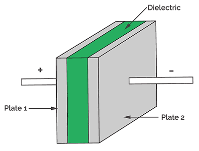
I've recently been trying to create a capacitor at home. Capacitors store charge on opposite sides of two parallel plates that have some kind of dielectric material between them. The dielectric material can be air or another substance with a higher dielectric constant. Here is a diagram of a capacitor:
Now I've found some tutorials online that show how to make some, and it looks pretty easy. However, most of these capacitors are only in the high picoFarad to low nanoFarad range, and for the rail gun project, I'll need capacitors that are in the microFarad (uF) range. Most of these homemade capacitors used designs where two aluminum foil sheets are separated by a piece of paper or tape. I found a video on YouTube, however, that details the construction of an electrolytic capacitor:
(from yt/RimstarOrg)
These capacitors are still simple to make, and they can have values of capacitance well into the uF range. Capacitance can be given by this formula:
So if you want to increase capacitance, you should have your dielectric, which sits in between the plates, to be very small, as this will decrease your d (distance) in the denominator. An electrolytic capacitor makes this easy since the dielectric layer is essentially a very thin layer of aluminum oxide that is produced when you induce a voltage into the electrolyte solution (baking soda and water) with two aluminum plates. I thought about using soda cans like in Rimstar's video, but I couldn't find an easy way to refine them into plates. I figured using aluminum foil would be a lot better anyway since it's much easier to get a lot of and to shape. The piece of foil that will develop the oxidized layer should be made large since this will increase your A (area), which is in the numerator of the capacitance equation. This piece will also be known as the anode and will be connected to the positive lead. You can see here how I cut out the anode from a larger sheet pressed flat, which you can do with a ruler or heavy book. I also gave it a protruding section where I could connect the positive wire.
(the anode I've cut here is roughly 44cmx8cm)
Next, I got to work on curling it up so it could fit into my container. I used a highlighter to help me roll it up. After that, I used a ruler to slide into the rolled column and expand it to make the distance between the foil larger so that the aluminum didn't make contact with itself.
I placed the foil from the second image into a random jar I found in my house, and then placed a thin piece of aluminum for the negative lead to connect to. I poured in some water and added a few tablespoons of baking soda. Then, I connected the jar capacitor to a double-A battery to start the oxidation.
I left it going for a bit, then switched the battery to a 9V and left it for a few hours. I also added some more baking soda. This method can definitely be improved upon. For example, I could've made a baking soda solution, mixed it before adding it into the jar, and then placed the aluminum inside. Instead, I poured in the powder last and then had to wait for it to dissolve without shaking it because I didn't want to disturb the aluminum foil structure I had already placed inside. Obvious improvements like this, as well as others, will be implemented in the next post I make on this, so that a suitable capacitance is available for the rail gun project.
I ended up reaching a maximum capacitance of around 1.4 mF or 1,400 uF. However, my multimeter's readings were showing high variation, and it would also drop to around 800 uF as well. This variance might've been from the fact that I don't have clip-on leads to connect with, so I was using my hands the best I could. I'd also gotten open load readings a few times, but I was able to fix this by adding more baking soda. My current theory for why that happened is that after using the baking soda to oxidize the aluminum, too much is used up, and there's not enough to act as an electrolyte for the solution. Here are some of the readings:
A friend of mine and I have been getting really interested in rail guns as of late. Rail guns harness the properties of electromagnetism to accelerate projectiles at high speeds. Here is a video of the U.S. Navy's rail gun, which can reportedly shoot rounds at up to Mach 7, firing:
(from yt/The Military Show)
Now, of course, we don't have the capabilities of creating a device that powerful yet, so we settled for trying to make it using some more obtainable means. The basic design of the rail gun is 2 conducting rails that are attached to capacitors of some kind. A conductive projectile is placed between the two rails, which completes the circuit and allows a current to flow. This current provides a magnetic force that propels the projectile off the rails. The capacitors in the design allow a significant pulse of current to flow through in a short amount of time. Here is a diagram of a basic rail gun:
This layout is very common in hobbyist rail guns and even in ones that become very powerful. Here is an example of a high-power rail gun using the design by Ziggy Zee:
Capacitors are a key aspect of the rail gun, and we're opting to try and make our own. A basic homemade capacitor can be made with aluminum foil and some kind of paper dielectric. However, these capacitors are usually only in the nF (nanofarad) range, and we'll be needing capacitance well into the hundreds of uF (microfarad) range. I'll detail more about capacitors and the design we're going to use in a separate line of posts. These capacitors will be placed in parallel (to increase capacitance) and will need to be easy to produce in large quantities because of this.
For the conducting rails and projectile, we are thinking of using copper since it's pretty cheap and easy to find in the shapes we need.
Power will likely be supplied by 9V batteries lined in series (to increase voltage), similar to how Ziggy Zee powered his rail gun.
In the next post, I'll show some design choices we are thinking of using and some reasons as to why.
It's been more than half a year since my last post. I wanted to make an update, but I lost interest in the project, and school was getting in the way. I decided I'd wait till most of my final exams were through and then finally post again. By that point, I'd lost the final genome produced by the EvidentialGene software that I had gotten to work as well as the images that went along with that process. I was switching my PC over from Ubuntu to Windows and had the file backed up to a USB I've since lost.
Now, in the last post, I said that I'd outline the process of obtaining the proprietary software needed to run the pipeline. I still have some notes from that time, and in the rest of this post, I'm going to do my best to recall anything of importance.
fastanrdb -
I don't have fastanrdb anymore or remember what files it came with since I misplaced the USB
The links provided also no longer work from when I used them
The link below is all I really know of that mentions exonerate or fastanrdb
I can't recall anymore which exact release worked for me, but I know it wasn't any of the ones above V4.6.4
Once you've downloaded the main file, look for a specific cd-hit program file, which you should just drag into the file you're using for the genome addition with evigene and other proprietary software
blastn and makeblastdb -
This one is pretty self-explanatory and is a well-known software
I just went to the NCBI BLAST website and downloaded what I needed
I know the info is pretty vague here, and I don't even have the final genome anymore, but it's been a long while since I covered this project, and my interests have changed. School's out now, though, which means I'll have more posts coming soon. I'm working on a homemade capacitor, which is just gonna be a small part of another big project I've planned!